
15 Trending House Design Drawing Types and Techniques Worth Knowing
Producing or reviewing a house design drawing effectively requires understanding that different drawing types, floor plans, elevations, sections, perspectives, each serve a distinct communication purpose, and knowing when and how to use each one improves both the design process and collaboration with building professionals. This guide covers fifteen house design drawing types and techniques, from quick concept sketches to detailed construction sections, addressing both the traditional hand-drawing skills and the digital tools now widely available for this work. Every idea addresses a genuine practical aspect of creating or interpreting these essential design communication documents.
Trend & Background
House design drawing has evolved considerably as digital tools, from accessible consumer design software to professional-grade CAD and BIM programs, have expanded who can produce reasonably sophisticated design drawings beyond architects and professional drafters alone. This accessibility hasn’t eliminated the value of understanding traditional drawing conventions and techniques, since digital tools still require users to understand what information each drawing type needs to communicate, floor plan versus elevation versus section, regardless of whether that drawing is ultimately produced by hand or through software. Hand sketching has also maintained genuine relevance even within an increasingly digital process, valued specifically for its speed and flexibility during the earliest, most exploratory stages of design thinking before committing to more time-intensive digital drawing.
Key Takeaways
- Different drawing types, floor plans, elevations, sections, and perspectives, each communicate genuinely different information about a design.
- Hand sketching remains valuable even in a digital design process, particularly for quickly exploring early ideas before committing to software.
- Learning basic drafting conventions improves communication between a homeowner and an architect, even without pursuing professional-level skill.
- Digital tools have expanded what’s accessible to non-professionals, but don’t replace understanding what each drawing type actually needs to show.
1. The Floor Plan as the Foundational Drawing
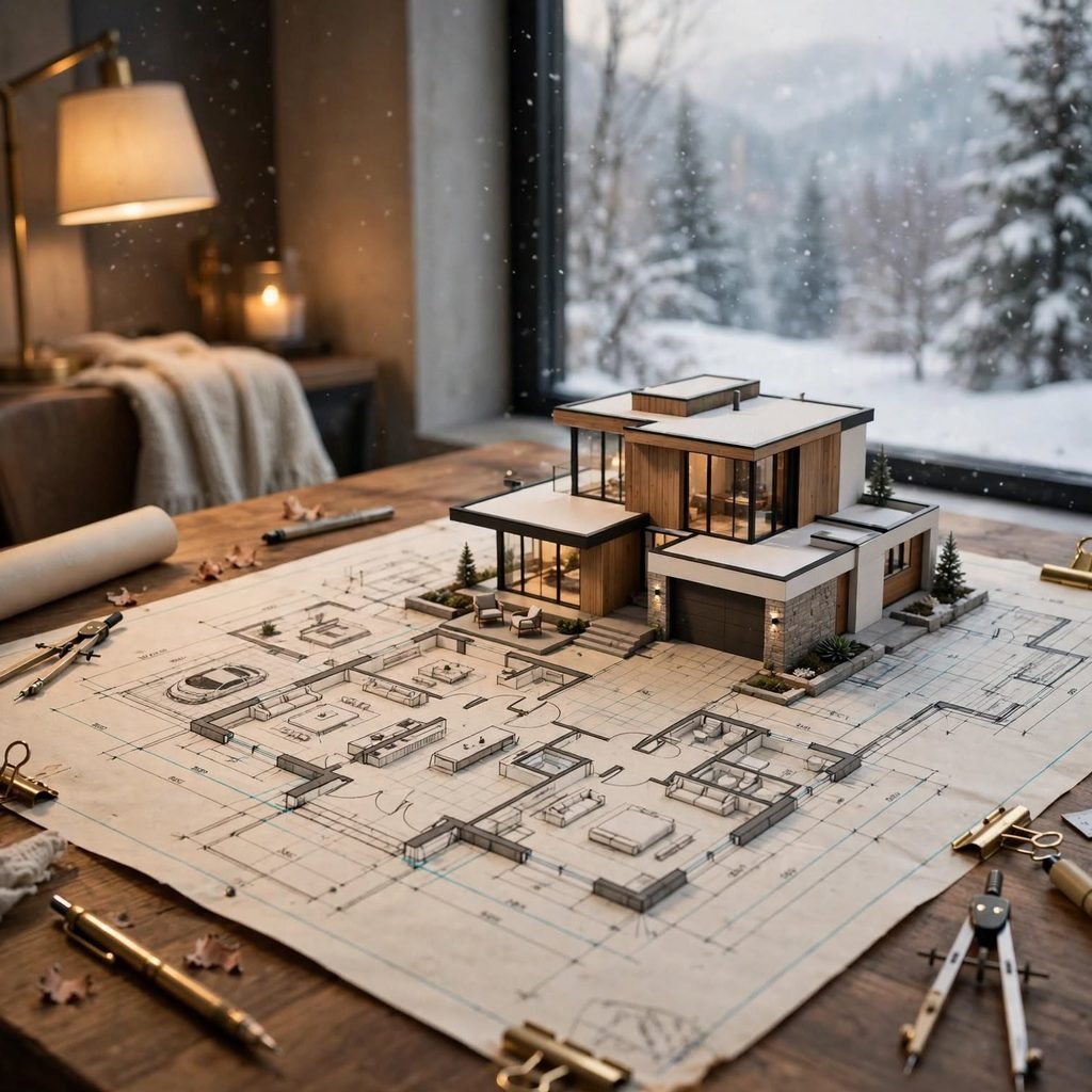
A floor plan, showing a building’s layout from directly above with walls, doors, windows, and room labels visible, serves as the foundational drawing most other house design documentation builds from, communicating room sizes, relationships, and circulation patterns more clearly than any other single drawing type. Learning to read and sketch basic floor plans, understanding standard wall thickness representation, door swing notation, and room labeling conventions, provides a genuinely useful foundational skill for anyone engaging with house design, whether producing original drawings or reviewing an architect’s proposed plans. Starting any house design process with rough floor plan sketches, even simple hand-drawn versions, helps establish basic spatial relationships before investing time in more detailed or technically precise drawings.
2. Elevation Drawings Showing Exterior Facades
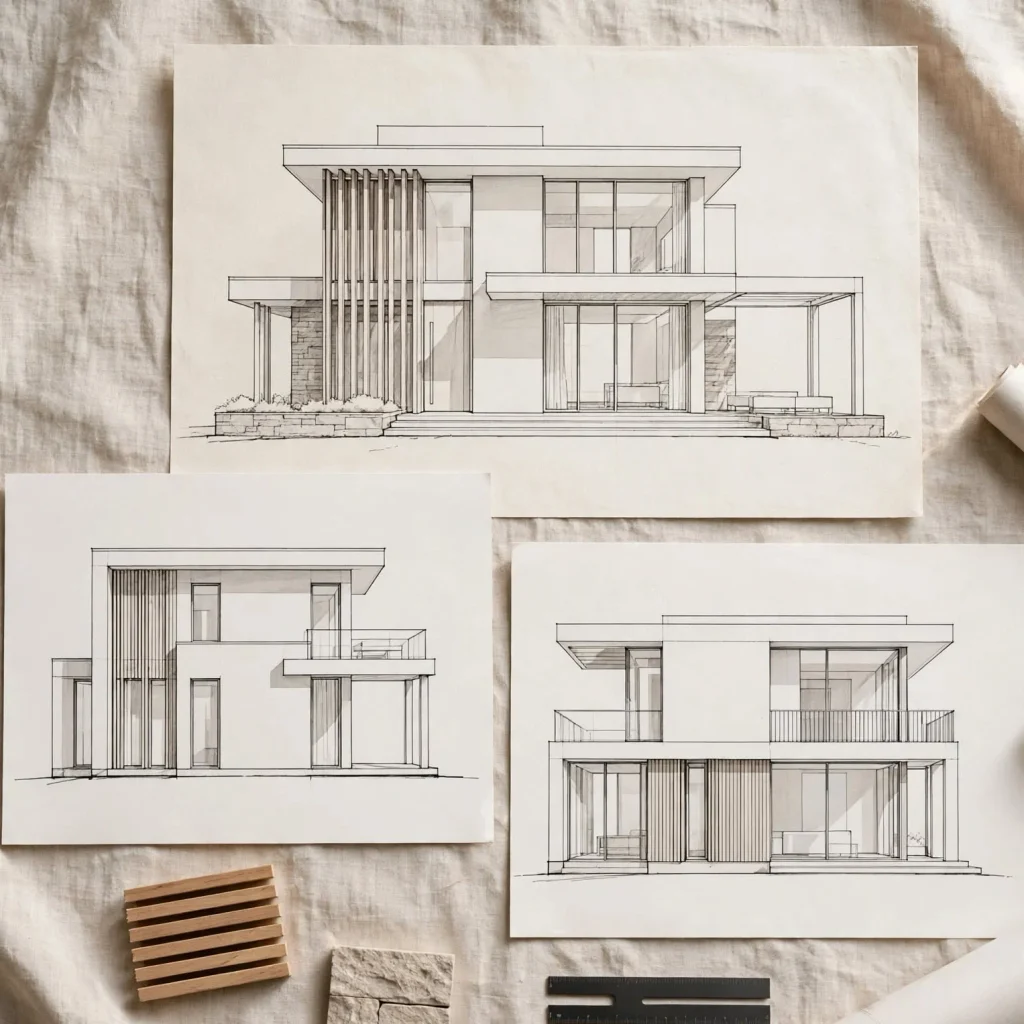
Elevation drawings, showing a building’s exterior facade from a straight-on, undistorted viewpoint for each of its sides, front, rear, and both sides, communicate a home’s actual exterior appearance, window and door placement, roofline, and material transitions in ways a floor plan alone cannot convey. Producing or reviewing all four elevations, not just the front facade most people naturally focus on, ensures a design’s full exterior character receives adequate consideration rather than only its most immediately visible side. This drawing type matters considerably for understanding how a design will actually look once built, making it worth genuine attention alongside floor plan review rather than treating elevations as a secondary afterthought.
3. Section Drawings Revealing Interior Structure and Volume
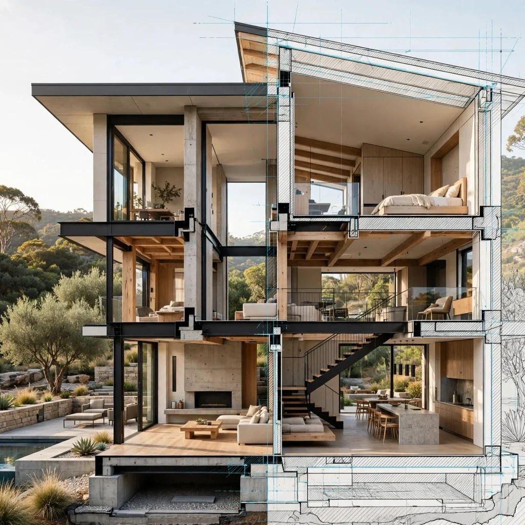
A section drawing, showing a building as though sliced vertically through a specific point, reveals interior ceiling heights, floor-to-floor relationships, and structural elements like stairs and roof framing in ways neither a floor plan nor an elevation can show on their own. This drawing type proves particularly valuable for understanding a design’s actual interior volume and spatial experience, information that a flat floor plan, showing only room outlines from above, doesn’t communicate about how a space will genuinely feel to move through. Requesting or producing at least one section drawing through a design’s most significant spaces, a great room or an area with notable ceiling height variation, provides genuinely useful information beyond what plan and elevation drawings alone convey.
| Drawing Type | What It Shows | Best Used For |
| Floor plan | Layout from above | Room relationships, circulation |
| Elevation | Exterior facade, straight-on | Exterior appearance, materials |
| Section | Vertical slice through building | Ceiling heights, interior volume |
| Perspective | Three-dimensional view | Overall visual impression |
4. Perspective Drawings for Genuine Visual Understanding
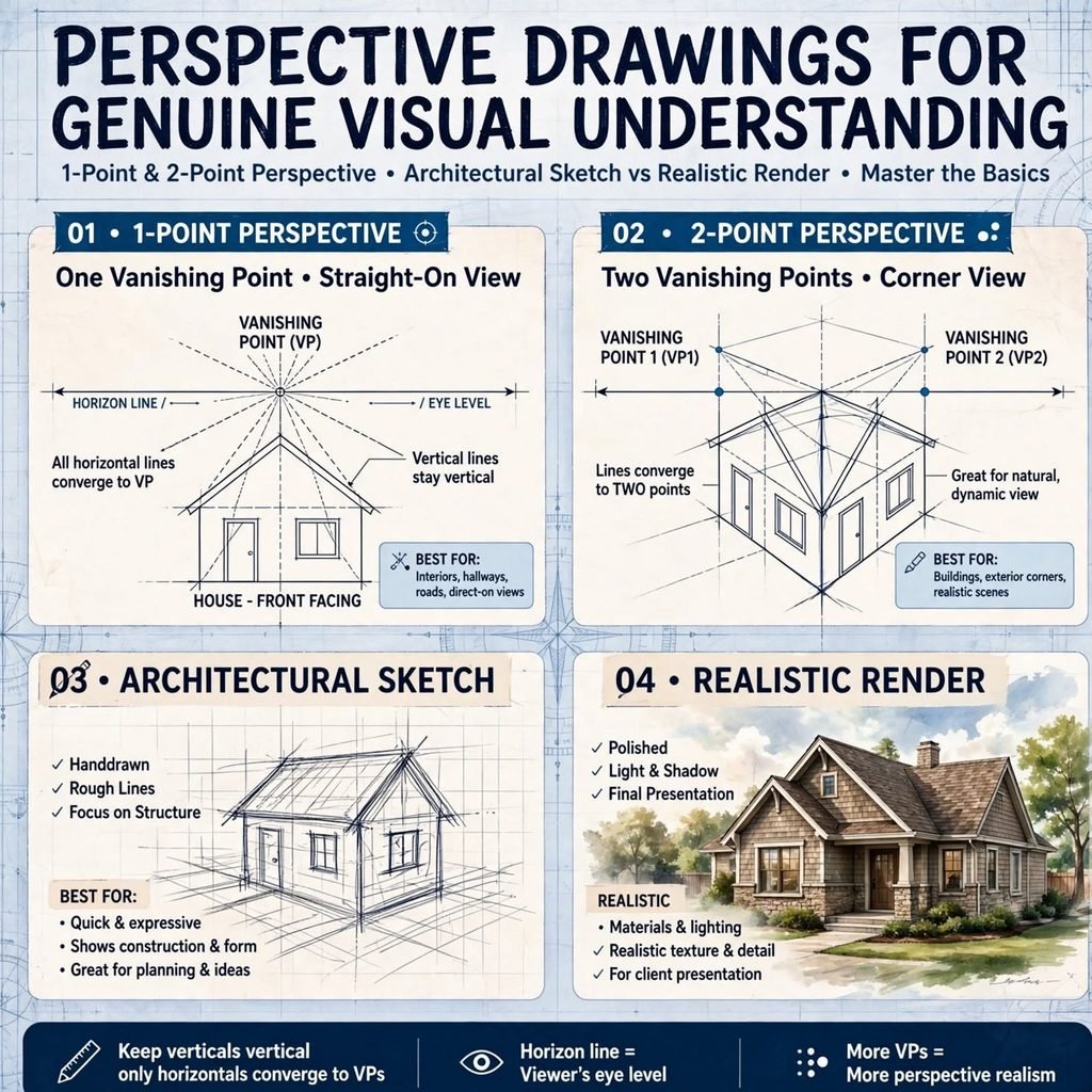
A perspective drawing, whether hand-rendered or digitally produced, shows a building or space in three-dimensional, realistic representation similar to how a camera or the human eye actually perceives it, providing a more intuitive, immediately understandable sense of a design’s genuine visual character than the more technical, abstracted floor plans, elevations, and sections. This drawing type works particularly well for communicating a design’s overall feel to someone without extensive technical drawing literacy, since a perspective view requires less specialized interpretation than a flat, scaled technical drawing. Requesting at least a few key perspective views, an exterior approach view, and one or two significant interior spaces, alongside more technical drawings, helps bridge the gap between abstract technical documentation and genuine visual understanding.
Looking for more inspiration to transform your home? Explore our collection of house design plans covering beautiful interiors, stylish exteriors, practical layouts, and cozy decorating inspiration for every type of home.
5. Quick Hand Sketching for Early Concept Exploration

Quick, loose hand sketches, produced rapidly without concern for precise scale or technical accuracy, remain genuinely valuable during a design process’s earliest, most exploratory stages, allowing rapid iteration through many possible layout or massing ideas before committing significant time to more precise digital or technical drawing. This sketching approach works well even for someone without formal drafting training, since the goal at this stage is exploring spatial relationships and basic ideas rather than producing a technically precise, presentation-ready drawing. Keeping these early sketches genuinely loose and quick, rather than becoming perfectionistic about line quality or precision at this exploratory stage, supports the rapid, iterative thinking this drawing approach is specifically meant to enable.
6. Understanding Standard Architectural Scale
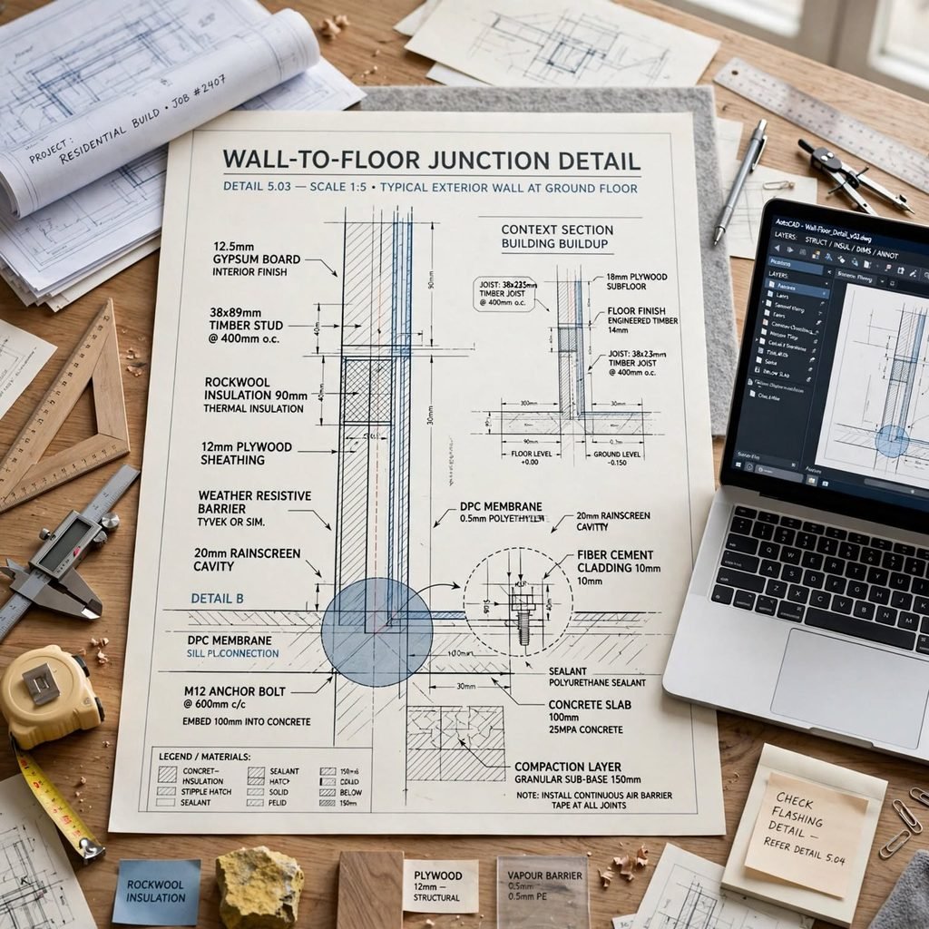
Working with standard architectural scale, most commonly one-quarter inch representing one foot for residential floor plans, allows drawings to accurately represent real-world dimensions in a manageable, readable format, and understanding this convention helps both in producing accurate drawings and in correctly interpreting dimensions from existing plans. Using an architect’s scale ruler, a specialized tool with multiple scale options marked along different edges, simplifies working at this consistent scale considerably compared to attempting manual calculation with a standard ruler. This scale literacy matters whether producing original drawings or reviewing plans an architect has provided, ensuring accurate understanding of actual room and building dimensions represented in the drawing.
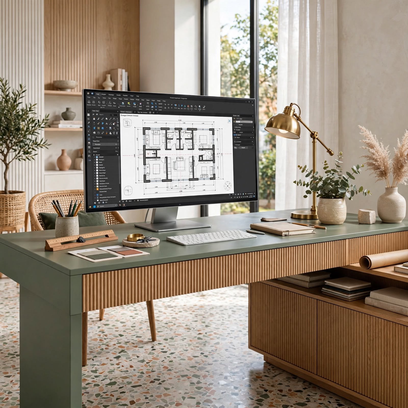
7. Digital CAD Software for Precision Drawing
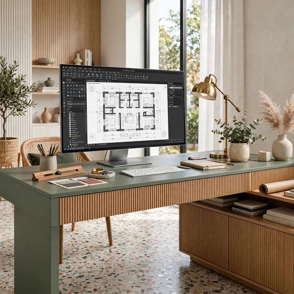
Computer-aided design software, ranging from professional-grade programs used by architects to more accessible consumer versions marketed toward homeowners and DIY designers, allows precise, easily revised drawing production that hand drafting cannot match in terms of accuracy and editing flexibility. These tools generally require some learning investment to use effectively, though many consumer-oriented programs have simplified their interfaces considerably to lower this learning barrier compared to professional architectural software. Choosing a software tool appropriate to the actual project’s complexity and the user’s genuine willingness to invest time in learning the program helps identify the right digital tool rather than either an overly simplified option lacking necessary features or an unnecessarily complex professional tool for a straightforward project.
8. Three-Dimensional Modeling for Spatial Understanding
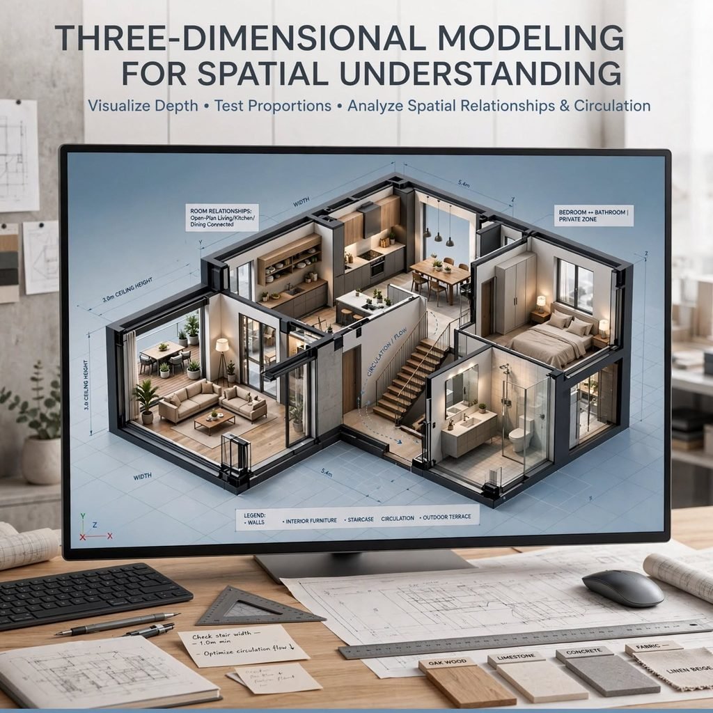
Building a genuine three-dimensional digital model of a proposed design, rather than working purely in two-dimensional plan and elevation drawings, provides considerably more intuitive spatial understanding, allowing a virtual walkthrough or rotation around the model to reveal how spaces actually relate and feel in three dimensions. This modeling approach has become increasingly accessible through both professional architectural software and more consumer-friendly three-dimensional design tools, expanding this capability beyond architects and professional designers alone. Building at least a basic three-dimensional model, even a simplified version without extensive material and finish detail, often reveals spatial issues or opportunities that flat, two-dimensional drawings alone don’t as readily communicate.
9. Site Plans Showing a Building’s Context
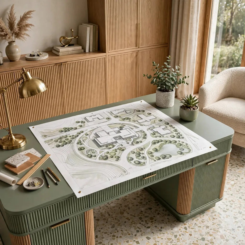
A site plan, showing a proposed building’s footprint positioned within its actual property boundaries, along with existing features like trees, driveways, and neighboring structures, communicates how a design relates to its genuine physical context in ways that floor plans and elevations, focused purely on the building itself, don’t address. This drawing type matters considerably for confirming a design actually fits within the site’s buildable area after accounting for setback requirements and existing site features, information essential for both design planning and eventual permitting approval. Producing or reviewing an accurate site plan early in the design process, based on genuine survey information rather than approximate estimation, prevents the serious problem of designing a home that doesn’t actually fit its intended site.
10. Detail Drawings for Specific Construction Elements
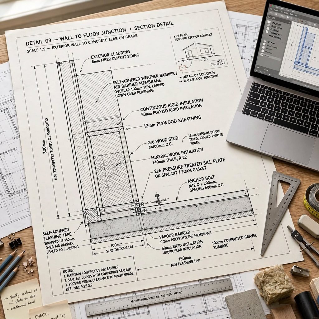
Detail drawings, showing a specific building element, a window installation, a stair construction, or a particular material transition, at a much larger scale than the overall building drawings, communicate the precise technical information builders need to correctly construct these specific elements. These drawings matter considerably more for actual construction execution than for general design communication with a homeowner, though understanding that this level of detail exists and will be needed helps set realistic expectations about the full scope of documentation a genuinely construction-ready plan set requires. Confirming that necessary detail drawings are included in a final construction document set, rather than assuming general plans alone provide sufficient guidance for these specific technical elements, prevents construction confusion or error.
11. Rendering Techniques for Presentation-Quality Visuals
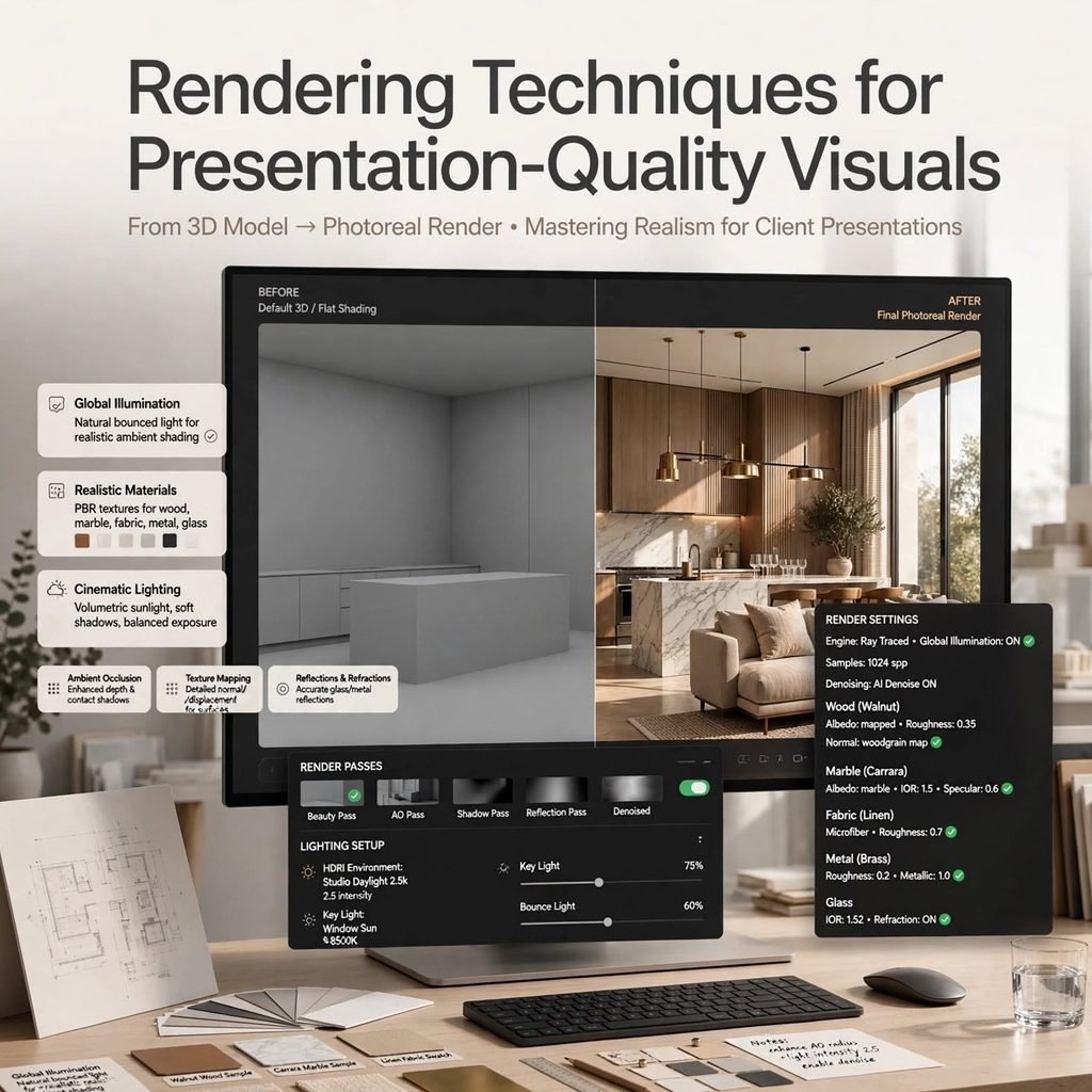
Rendering, whether traditional hand-coloring and shading techniques or digital rendering software that applies realistic materials, lighting, and shadow to a three-dimensional model, transforms a technical drawing into a more visually compelling, presentation-quality image useful for genuinely communicating a design’s aesthetic character to clients, homeowners, or for permitting and marketing purposes. This additional rendering step requires meaningful additional time and, for digital rendering, often specialized software or rendering service costs beyond basic drawing production. Requesting rendered views specifically for key spaces or exterior perspectives, rather than assuming basic technical drawings alone will adequately communicate a design’s genuine visual impact to non-technical audiences, helps bridge this communication gap when needed.
12. Understanding Line Weight and Drawing Hierarchy
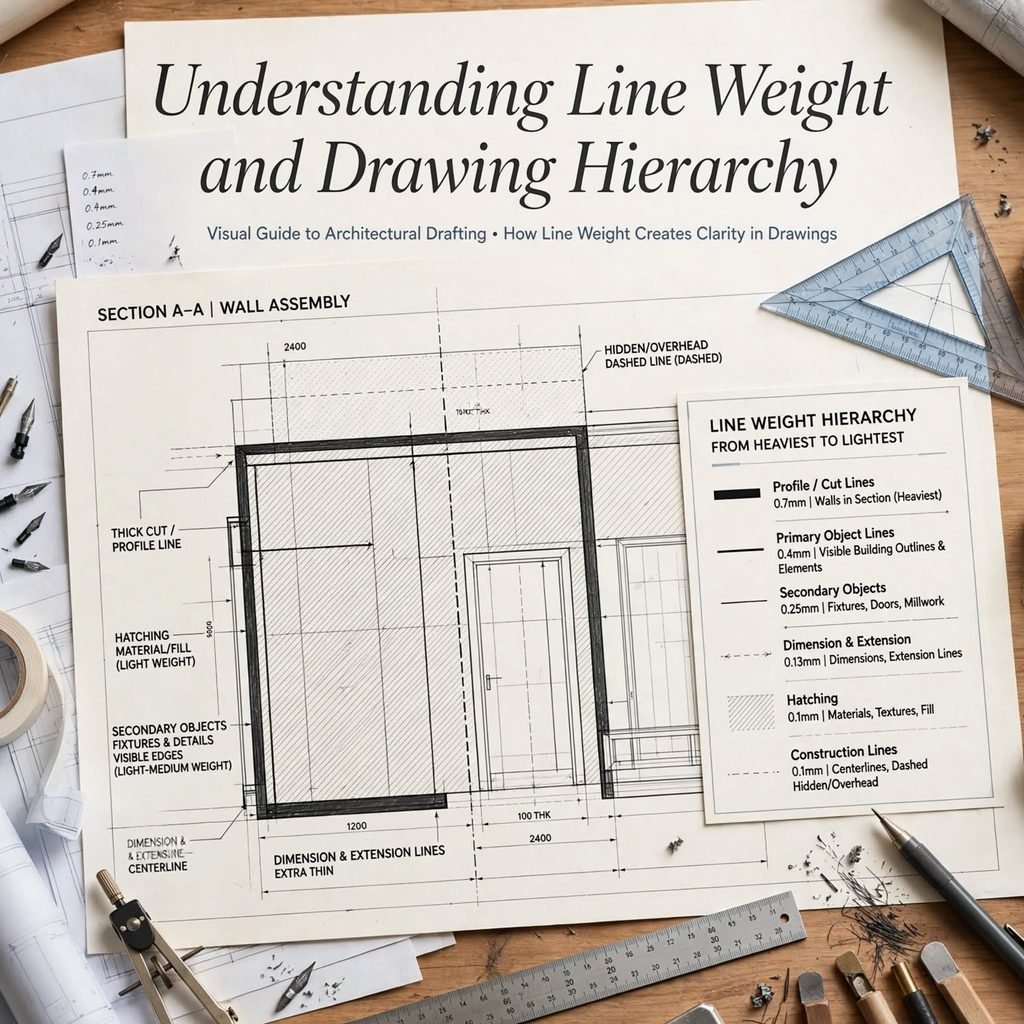
Learning to read and apply appropriate line weight variation, using heavier, darker lines for elements like exterior walls and lighter lines for less structurally significant details like furniture or dimension lines, helps both in producing clearer drawings and in correctly interpreting the relative importance of different elements within an existing drawing. This hierarchy convention helps a drawing communicate more efficiently, allowing a viewer’s eye to quickly distinguish primary structural information from secondary or reference details without requiring extensive verbal explanation. Practicing this line weight variation, even in basic hand sketches, produces noticeably clearer, more professional-reading drawings than uniform line weight throughout.
13. Working From Existing Conditions Drawings for Renovation Projects
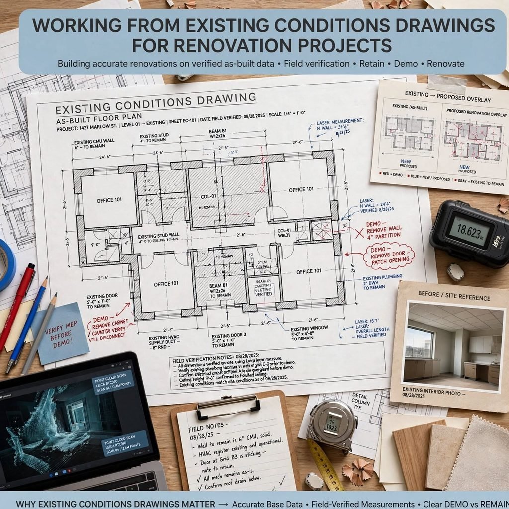
For a renovation or addition project, producing or obtaining accurate existing conditions drawings, precisely documenting a home’s current layout, dimensions, and structural elements before any new design work begins, provides the essential accurate foundation any proposed renovation design must genuinely build from. Skipping this step, or working from inaccurate or outdated existing drawings, risks designing a renovation that doesn’t actually fit or properly integrate with the home’s real current conditions once construction reveals discrepancies. Physically measuring and documenting a home’s actual current conditions, rather than relying on assumed or remembered dimensions, or original builder plans that may not reflect changes made over the years, ensures this foundational documentation is genuinely accurate.
14. Collaborative Digital Platforms for Client and Team Review

Digital platforms and file formats that allow multiple parties, an architect, a homeowner, various contractors, to view, comment on, and sometimes directly mark up shared drawings remotely have made the collaborative review process considerably more efficient than the traditional practice of physically distributing and marking up paper drawing sets. These tools work particularly well for keeping a project’s various stakeholders genuinely aligned throughout an extended design and construction process, reducing the miscommunication risk that can occur when different parties work from different versions of evolving drawings. Establishing clear expectations early about which platform and file-sharing approach a specific project will use helps ensure all parties stay coordinated around the same current, accurate drawing set throughout the process.
15. Knowing When Professional Drawing Skill Is Genuinely Required
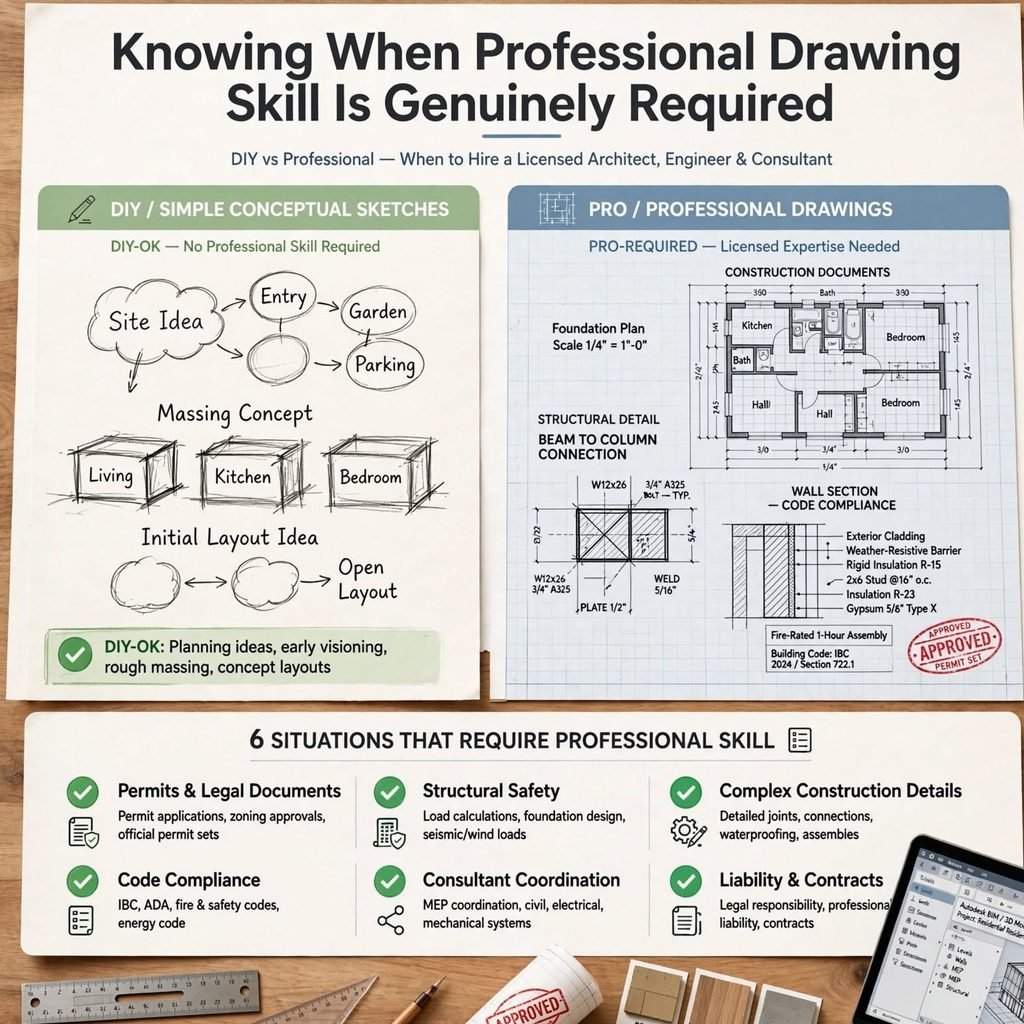
Recognizing the genuine limits of amateur or homeowner-produced house design drawings, understanding that final construction documents require professional-level technical accuracy, code knowledge, and often licensed stamping regardless of how skilled an individual’s personal sketching or digital drawing ability might be, prevents the risky assumption that personally produced drawings alone are sufficient for actual construction and permitting purposes. Amateur sketches and digital models remain genuinely valuable for exploring ideas, communicating preferences to a professional, and better understanding proposed designs, but this personal drawing work should generally feed into and inform, rather than replace, the professional documentation process a genuine construction project requires. Being honest about this distinction, valuing personal drawing skill for its genuine communication and exploration purpose while still engaging appropriate professional expertise for final construction documentation, produces the most successful overall outcome.
Shop the Look
Developing house design drawing literacy starts with understanding what each drawing type actually communicates: practice reading and sketching basic floor plans first, since they form the foundation most other drawings build from, then move to elevations and at least one section drawing to understand exterior appearance and interior volume. Use quick hand sketches for early idea exploration before investing time in more precise digital drawing, and learn basic scale and line weight conventions to both produce and interpret drawings more effectively. For any project actually moving toward construction, ensure professional involvement for final, code-compliant documentation regardless of personal drawing skill developed along the way.
Common Mistake to Avoid
A common mistake in house design drawing is treating a single drawing type, most often the floor plan, as sufficient to fully understand or communicate a proposed design, without also reviewing elevations, sections, or perspective views that reveal genuinely different, essential information about how a design will actually look and feel once built. A floor plan alone can’t communicate a home’s exterior character, its interior ceiling heights and volume, or its genuine three-dimensional spatial experience, meaning relying on floor plan review alone risks significant surprises once construction reveals the fuller design. Reviewing a design through multiple complementary drawing types, rather than any single drawing in isolation, produces a far more complete and accurate understanding before committing to construction.
FAQs
Do I need to learn to draw well to participate in my house design process?
Genuine artistic drawing skill isn’t necessary to meaningfully participate in a house design process, since even rough, imprecise sketches effectively communicate basic spatial ideas and preferences to an architect, and much of genuinely useful plan review involves reading and understanding professionally produced drawings rather than personally creating polished ones. Learning basic conventions, how to read a floor plan’s scale and symbols, and understanding what different drawing types show provides more practical value for most homeowners than developing personal rendering or fine drafting skill. Focusing on this reading and basic communication literacy, rather than feeling pressure to produce professional-quality drawings personally, supports effective participation in the design process without requiring specialized artistic training.
What’s the best software for a homeowner to use for basic house design drawing?
Several consumer-oriented design software options exist specifically marketed toward homeowners and non-professionals, generally offering simplified interfaces and guided workflows compared to professional architectural software, making them a reasonable starting point for basic floor plan sketching or visualization without extensive technical training. The right specific choice depends on a project’s actual complexity and the user’s comfort level with software generally, with some tools prioritizing ease of use for simple projects while others offer more capability at the cost of a steeper learning curve. Trying a few different free or trial versions of these consumer tools often helps identify which specific program’s workflow and capability genuinely suits a particular user’s needs and comfort level.
Why do I need a section drawing if I already have floor plans and elevations?
A section drawing reveals information that neither a floor plan, showing layout from directly above, nor an elevation, showing only a flat exterior facade, can communicate, specifically interior ceiling heights, how different floor levels relate vertically, and the genuine spatial volume and experience of moving through a space. This information matters considerably for understanding how a design will actually feel to occupy, information that’s easy to overlook when reviewing only plan and elevation drawings that don’t directly show this vertical, volumetric dimension. Requesting at least one section drawing through a design’s most significant or spatially interesting areas provides genuinely valuable information that complements, rather than duplicates, what plan and elevation drawings alone convey.
Can I use hand-drawn sketches as the actual construction documents for my project?
Hand-drawn sketches, however detailed, generally cannot serve as final construction documents for an actual building project, since construction documents require the precision, completeness, and often professional licensing stamp that formal, typically computer-produced drawings provide to meet building code and permitting requirements. Hand sketches remain genuinely valuable during earlier design exploration and for communicating ideas and preferences to a professional, but this personal work should feed into, rather than replace, the formal technical documentation process a licensed architect or engineer ultimately needs to produce for actual construction. Understanding this distinction between exploratory personal sketching and genuine construction-ready documentation prevents the risky assumption that informal drawings alone are sufficient for actual building.
How do I know if I’m reading a house design drawing correctly?
Checking a drawing’s included legend or key, which typically explains any specialized symbols and notation used, along with confirming you understand the stated scale and are measuring or interpreting dimensions accordingly, provides the basic foundation for accurate drawing interpretation. When genuine uncertainty remains about what a specific element or notation represents, asking the architect or drafter directly for clarification, rather than guessing or assuming, prevents misunderstanding that could lead to costly confusion later in a project. Building general familiarity with common architectural drawing conventions over time, through this kind of direct engagement and clarification during actual projects, gradually improves genuine drawing literacy more effectively than attempting to master every convention in the abstract before ever working with real project drawings.
Conclusion
Understanding house design drawings, the distinct purpose of floor plans, elevations, sections, and perspectives, along with basic conventions for scale and interpretation, meaningfully improves both personal engagement with a design process and communication with the architects and professionals ultimately responsible for producing genuine construction-ready documentation. Save this guide to Pinterest for reference while planning your next project, and check out our related post on house design plans for more on how these individual drawing types combine into a complete, buildable plan set.